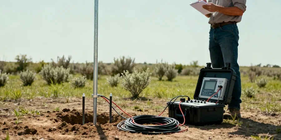
In Boston, the contrast between historic fill, glacial till, and buried bedrock creates a subsurface environment where conventional drilling alone rarely tells the full story. We use electrical resistivity and vertical electrical sounding to map these transitions without extensive disturbance, which proves critical in neighborhoods like Back Bay and South Boston where much of the ground is artificial fill over former tidal flats. The method works by injecting current into the ground and measuring how the soil resists flow; fine-grained marine clays read differently than coarse outwash or intact argillite. For projects near the Charles River or along the I-93 corridor, this geophysical approach helps identify paleochannels, groundwater pathways, and depth to refusal before committing to a full drilling program. We often pair resistivity profiles with seismic refraction when bedrock rippability is in question, or with test pits where utility clearance allows direct correlation of the geophysical signature. The goal is a defensible ground model that holds up under peer review by Boston-area geotechnical boards.
A resistivity contrast of two orders of magnitude between saturated fill and intact Cambridge Argillite makes VES one of the most cost-effective reconnaissance tools in the Boston Basin.
Site-specific factors
Boston's expansion over the past two centuries buried creeks, mill ponds, and tidal flats beneath a patchwork of fill that ranges from clean sand to demolition debris and harbor dredge. The 1920s construction of the subway and the Big Dig in the 1990s compounded the underground complexity with slurry walls, abandoned conduits, and utility corridors that distort geophysical signals. Skipping a resistivity survey in this setting means drillers may hit obstructions, misinterpret refusal as bedrock, or miss a buried channel that later causes differential settlement. A VES sounding line run perpendicular to the Shawmut Peninsula's historic shoreline, for example, can reveal where the fill-thickness changes abruptly, information that directly influences excavation support design and dewatering requirements. We process the data with inversion software that accounts for the urban noise floor, and we ground-truth the resistivity model with at least one boring or CPT sounding to anchor the interpretation in measured soil behavior.
Questions and answers
How deep can electrical resistivity surveys investigate in Boston's urban environment?
Practical investigation depth runs between 20 and 100 feet, controlled by array length and site access. In downtown Boston the limiting factor is often space for electrode layout rather than the method itself. For targets deeper than 100 feet we typically combine resistivity with seismic refraction to maintain resolution.
What does a VES survey cost for a typical Boston foundation project?
For a standard vertical electrical sounding with several expansion steps and a basic inversion report, budgets in the Greater Boston area run between US$570 and US$1,030 per sounding location. The final figure depends on the number of soundings, site access constraints, and whether we integrate the data with existing boring logs.
How do you handle interference from the MBTA and underground utilities?
Urban noise is part of every Boston resistivity survey. We use stacking routines that average multiple readings at each electrode spacing, apply a 60 Hz notch filter to suppress traction-power interference, and schedule surveys during lower-noise windows when possible. Metallic utilities are noted on the site plan so their influence on the resistivity profile can be identified during interpretation.